 Zentek Studio
Zentek Studio is a free 2D drafting + 3D solid modeling CAD app. If you've used other CAD applications, most of this will feel familiar — this guide focuses on the handful of things that are specific to Zentek Studio, so you're productive fast. You don't have to read it top to bottom: sections 1–2 are the essentials, 3–4 are hands-on walkthroughs, and 5–7 are reference.
1The workspace
Five regions. Everything in this guide refers to them by these names.
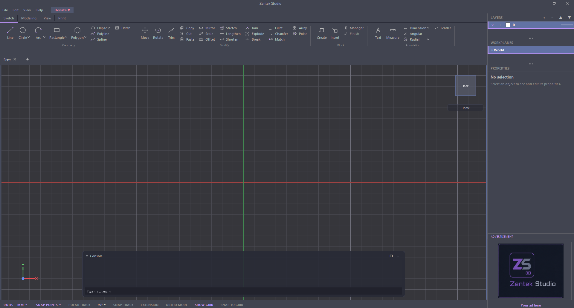
- Ribbon
- The tabbed toolbar at the top with four tabs — Sketch (2D), Modeling (3D), View, and Print. Almost every command lives here.
- Canvas
- Where you draw. Z is up: the ground plane is X/Y, and Z is elevation.
- Right dock
- Three stacked panels — Layers on top, Workplanes in the middle, Properties below. Workplanes lists the surfaces you can sketch on, and Properties updates to show whatever you have selected.
- Status bar
- The bottom strip: the Units control on the left, then the drafting toggles (object snap, ortho, grid, polar…). An active toggle is purple.
- Console
- The floating panel over the canvas: the log of what happened, the prompt for the current step (with mode chips when a step offers alternatives), and the command line at the bottom for launching commands by name. See The console.
The menu bar is deliberately small — just File, Edit, View, Help. There is no "Draw" or "Modify" menu: those commands live on the ribbon's Sketch and Modeling tabs.
2Driving the app
The interaction model — read this once and everything else clicks into place.
Starting a command
- Click a ribbon button, or type its name in the command line — typing
lithen Enter starts Line. - Some buttons are split buttons: click the button body for the default, or click the small caret for construction variants — e.g. Circle -> 2 points, Rectangle -> Rotated.
- With nothing running, Enter repeats your last command.
Typing values — the dynamic input
Small labelled fields float next to the cursor while a command runs. Type into them and:
- Formulas work. Typing
20+30enters50(also*/^and parentheses). - Tab / Shift+Tab move between fields; ↑/↓ change the command's mode (also shown as clickable chips).
- Enter submits, Esc steps back (see below).
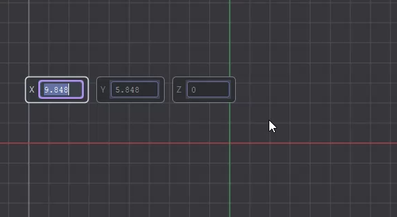
The floating fields only appear while the cursor is over the canvas. Start a command from the ribbon and nothing shows until you move onto the drawing.
The console
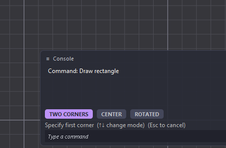
The console floats over the canvas and is where the app talks back. Reading down, it holds the log of what has happened, the prompt for the step you are on — with mode chips above it when that step offers alternatives — and the command line at the very bottom.
Mode chips
When a step offers more than one way to build the same thing, the console shows those alternatives as chips. The active one is highlighted; click a chip, or press ↑/↓, to switch. Switching restarts the current construction, so you can change your mind mid-command.
The command line
The field at the bottom of the console launches commands by name — you never have to hunt the ribbon for something you already know. Start typing and a list of matches drops down.
- Type any part of the name. Matching is on substrings, not just the start, so
linfinds Line but also Spline, Cylinder and Polyline. - Several words narrow it down. Every word you type has to appear somewhere in the name, so
3d rgets you to 3D Rotate. - The best match is already selected — matches that begin a word rank above mid-word ones, so
liputs Line ahead of Polyline. Press Enter to run it straight away. - ↑/↓ move down the list, and the highlighted command starts on its own shortly after you stop — no Enter needed. Clicking a row runs it too.
- Esc clears the line, and cancels a running command.
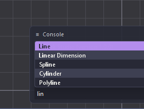
lin lists every command containing those letters, with Line
highlighted as the best match — Enter runs it.The command line only launches. Once a command is running, the floating fields at the cursor take over the typing — that is where values and coordinates go.
Enter and Esc
- Enter — confirm the current step / accept the live preview.
- Esc — step back one stage, not always a full cancel. Watch the prompt's hint: (Esc to cancel) on the first step, (Esc to go back) on later ones, (Esc to finish) for chaining commands.
Entering coordinates
- Absolute point:
X,YorX,Y,Z(commas or spaces). - Relative polar:
@length<angle(angle in degrees). There is no@dx,dy— relative offsets are a per-command Absolute/Relative mode you toggle with ↑/↓ in Move/Copy. - Per-value units: suffix any number to override the drawing unit —
2in,5mm,3",1'.
Drafting aids & snapping
Toggle these from the status bar or with function keys. An object snap always wins over grid and ortho, and the snapped point also sets the working elevation (Z).
| Key | Toggle | What it does |
|---|---|---|
| F3 | Object Snap | Snap to Endpoint / Midpoint / Center / Quadrant / Intersection / Perpendicular / Tangent / Nearest (pick which in the SNAP POINTS ▾ menu). |
| F8 | Ortho Mode | Constrain to horizontal / vertical. Mutually exclusive with Polar. |
| F10 | Polar Track | Snap the direction to fixed angle steps (90°, 45°…). |
| F7 | Show Grid | Show/hide the reference grid. |
| F9 | Snap to Grid | Snap the cursor to grid points. |
| F11 | Snap Track | Line up against points you've already snapped to. |
Two snaps stacked on the same spot? When one snap point sits right behind another — a box's far corner hidden behind its near one when you look at it head-on — hover the spot and press Tab to cycle through the stacked snaps until the one you want lights up. Moving the cursor resets it.
Units
The UNITS control on the status bar (MM ▾) switches between millimetres,
centimetres, metres, inches, and feet.
Switching units never resizes your geometry — it only changes how lengths are shown and how
typed numbers are read. A 25.4 mm line simply reads as 25.4 in mm or 1
in inches.
Moving around the view
| Action | Do this |
|---|---|
| Orbit (3D) | Right-drag |
| Pan | Middle-drag |
| Zoom | Mouse wheel |
| Zoom Window | Press Z, then drag a box (plain Z — Ctrl+Z is Undo) |
| Zoom Extents | Ctrl+Shift+E (or View menu) |
| Select | Left-click; or drag a box — left->right = window (enclose), right->left = crossing (touch) |
| Add / remove from selection | Shift+click |
| Edit text / hatch / leader | Double-click it |
3Your first 2D part
A 100 × 60 plate with a rounded corner, a hole, and a dimension. ~5 minutes.
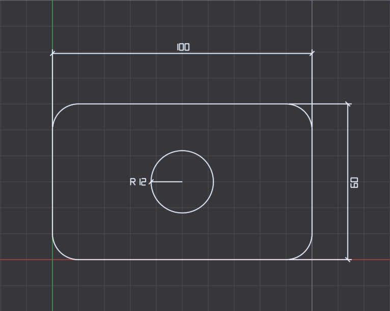
- New drawing. Ctrl+N. Make sure Object Snap is on (F3 — the status-bar SNAP POINTS button turns purple).
- Draw the outline. On the Sketch▸Geometry▸Rectangle button pick Two corners.
At Specify first corner type
0,0Enter; at Specify opposite corner type100,60Enter. - Add a hole. Sketch▸Geometry▸Circle (Center, radius).
At Specify center point type
50,30Enter; at Specify radius type12Enter. - Round a corner. Sketch▸Modify▸Fillet.
At Specify radius type
10Enter, then click the two edges that meet at one corner (Select first object -> Select second object). A tangent arc replaces the corner. - Dimension it. Sketch▸Annotation▸Dimension (Aligned). Snap the two bottom corners (first / second extension line origin), then move away from the part and click to place the dimension line. Dimensions chain — press Esc to end.
- Save. Ctrl+S, name it, and it's written as a
.zsdfile.
Prefer clicking to typing? Every "type X,Y" step can be a click on the canvas instead —
object snap will grab exact corners, midpoints, and centers for you.
4Make it 3D
Turn the plate you just drew into a solid, then look at it from every side and export it for printing. ~5 minutes.
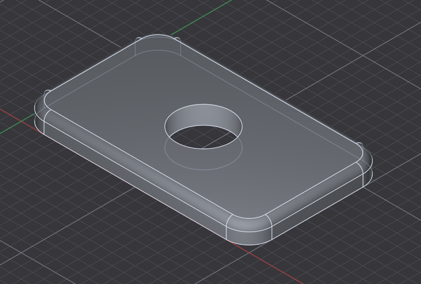
- Switch to 3D. Click the Modeling ribbon tab. Your plate is still on screen — 2D geometry and solids share one model space, so there is nothing to import or convert.
- Extrude the outline. Modeling▸Feature▸Extrude.
Select the plate outline and press Enter; at
Specify extrusion height type
8Enter. The closed outline — rounded corner and all — becomes a solid plate 8 mm thick. - Cut the hole. Run Extrude again, this time selecting the circle, and give it a height that passes all the way through the plate. A profile extruded into an existing solid cuts it rather than adding to it — the console confirms with Extrude: cut 1 solid(s).
- Look around. Right-drag to orbit, middle-drag to pan, wheel to zoom — or use View menu ▸ Isometric for a clean 3/4 view. Orbit spins around whatever is under the cursor when you press, so point at the feature you want to inspect and drag. Selecting objects never moves the view; use View menu ▸ Zoom to Selection when you want to frame what you picked.
- Refine it. Try Modeling▸Modify▸Fillet Edge to round the plate's top edges, or Shell to hollow it — pick the edges/faces and enter a value when prompted. To cut one solid out of another, place a second overlapping solid and use Modeling▸Boolean▸Subtract.
- Sketch on a face. Modeling▸Modify▸Select Workplane, then click a flat face. That face becomes your drawing plane: every 2D command now draws directly on it, and coordinates read in the face's own frame instead of the ground plane's. Press Esc to go back to World.
- Export. File ▸ Export ▸ STL writes a mesh ready for 3D printing or slicing. File ▸ Export ▸ STEP writes exact surfaces instead of triangles, for another CAD package.
The Workplanes panel. Every face you pick becomes a named plane (Plane 1, Plane 2, …) in the Workplanes panel of the right dock, with ⌂ World pinned at the top for the ground plane. Click a row to sketch there again; right-click a plane to Rename or Delete it. Picking the same face twice reuses its plane rather than stacking duplicates. Deleting a plane leaves the geometry you drew on it untouched, releasing it back to World.
Analytic vs Mesh. While placing a primitive, chips let you pick the body's nature with ↑/↓: Analytic (the default) keeps exact, true curves — best for precise parts; Mesh is a freeform triangle body. Some freeform edits convert a body to Mesh and will warn you first.
Push/Pull works on flat faces. Click a planar face and drag along its normal — pull adds material, push carves it away. A curved wall (like a cylinder side) highlights but won't push; change its size through its grip or the Properties panel instead.
5Essentials
Layers
In the Layers panel (top of the right dock): + new adds a layer, ▲/▼ reorder. Single-click a row to make it current (new objects land on the current layer). Each row has a V (visible) and L (lock) toggle, a colour swatch, and a linetype preview.
Note Layer 0 is protected — it can't be renamed, deleted, or recoloured. Deleting a layer can't be undone.
Properties
Select one object to see its properties; single-click a value to edit it (fields take formulas and unit suffixes). Set a per-object Color / Linetype / Lineweight under Appearance — By Layer means "inherit the layer" (blocks show By Block).
Select several objects to edit their shared properties at once; differing
values read *VARIES*.
Files & formats
- Drawings save as
.zsd; reusable blocks as.zsb. - Open opens each drawing in a new tab.
- Import: DXF, STL, OBJ. Export: DXF, STL, STEP, OBJ.
- Print: File ▸ Print Preview, then Print or Export image.
Safety net & feedback
- Autosave. If the app closes unexpectedly, the next launch offers to recover unsaved drawings.
- Found a bug? Help ▸ Report a Bug / Suggestion… — optionally attaches your drawing and opens a pre-filled email.
6Keyboard & mouse
| Keys | Action |
|---|---|
| Ctrl+N / Ctrl+O | New / Open (new tab) |
| Ctrl+S / Ctrl+Shift+S | Save / Save As |
| Ctrl+Z / Ctrl+Y | Undo / Redo |
| Ctrl+C / X / V | Copy / Cut / Paste |
| Ctrl+A / Delete | Select All / Delete |
| Enter | Confirm step · (idle) repeat last command |
| Esc | Step back one stage · cancel a grip drag |
| Tab · ↑↓ | Next input field / cycle stacked snaps · change command mode |
| Z · Ctrl+Shift+E · Ctrl+Shift+F | Zoom Window · Zoom Extents · Zoom to Selection |
| F3 F7 F8 F9 F10 F11 | Object snap · grid · ortho · grid snap · polar · snap track |
| Right-drag · Middle-drag · Wheel | Orbit · Pan · Zoom |
7Tips that save you time
- Type math into any field.
20+30,2*15,(10+5)/2all work. - Line makes separate segments. Each click is its own Line entity (one Ctrl+Z removes one segment). For a single connected shape, use Polyline.
- Mind the split-button carets. The construction variants (Circle 2 points, Arc Start, center, end, Rectangle Rotated…) hide behind the little caret.
- Object snap changes your Z. Snapping to a point adopts that point's elevation for the next picks — handy in 3D, surprising in 2D if you didn't expect it.
- Lock the view for 2D work. Set the view you want first (Top for flat drafting), then click the little padlock in the top right of the view cube. Rotation is off until you click it again, so a stray right-drag cannot knock the drawing out of alignment. Panning and zoom still work; the cube faces and View presets are frozen too, which is why you set the view first.
- No Extend or Erase button. Extend is a mode of Lengthen; erase is the Delete key.
- Grip editing. Select an object (no command running) and drag the little square handles to reshape it directly.
- Repeat fast. Press Enter on an empty canvas to run the last command again — great for placing several primitives or circles.
That's the whole model. When something asks for a point, you can always click, type coordinates, or type a length/angle — and Esc walks you back if you change your mind. Explore the ribbon; every command follows the same rhythm.